Dec 29 & 30
I had researched installing a new Oil Temp. Gauge and a found that a common solution was to use an identical temperature sensor as used for the coolant temp. gauge and share the existing gauge by means of a switch. I had purchased an additional sensor some time ago.

Temp sensor fitted in oil sump bung

Temp sensor fitted in oil sump bung.
First job was to remove the sump oil drain bung, thus draining the oil.
Then, I installed the sensor into the oil drain bung by drilling a 9mm hole in the center and tapping a 10mm x 1mm pitch thread. Then refitted the bung & re-filled the oil. I ran a new green wire from the sensor to the back of the dash panel.

Oil sump bung fitted in place with new wiring

Temp gauge removed from dash
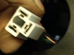
Temp gauge 3 pin connector
Next job was to remove the water temperature gauge from the dash panel. Its held in place with a U bracket and 2 thumb-wheel nuts. Then unplug the 3 spade connector fitting.

Original temp gauge wiring

After cutting the 3 pin connector
I had to separate out the feed wire and spade connector from the others and did this by cutting with a Stanley knife & wire cutters.

New wiring with switch and added green wire to oil temp sensor
Next I made up a harness with a changeover switch. The center pin of the switch was soldered to a wire with a female spade connector leading to the gauge signal pin. The first side pin of the switch was soldered to a wire with a male spade connector that will connect to the original water temp signal. Last pin is soldered to the green wire coming from the new sender on the sump. All solder joints were completed with heat shrink sleeving. Then plug it all together and install the gauge back in the dash panel. Oh, and before that drill a 3/8″ diameter hole below the gauge to install the switch.
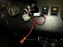
Wiring installed, waiting for gauge to go in

Completed gauge wiring, ready for gauge to go back into dash

New oil/coolant switch under temp gauge
The switch changes the gauge to read either coolant temperature or oil temperature.


